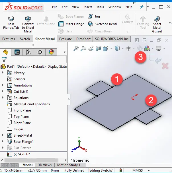

NoteThe parameters that you define in the Base Flange PropertyManager are taken as the defaultparameters throughout the current document. The various options available in the Base FlangePropertyManager are discussed next. The BaseFlange PropertyManager is displayed as shown in Figure 16-3 and the preview of the baseflange is displayed with the default values. To create a base flange, draw the sketch of the baseįlange and then choose the Base-Flange/Tab button from the Sheet Metal toolbar. You can create a base flange from aclosed sketch or an open sketch. The various toolsused to create the sheet metal components are discussed next.įor creating a sheet metal component, first you need to create a base feature or a basesheet. In thismethod, you will define all the parameters related to the sheet metal such as the bendingradius, the bend allowance, and the relief while creating the base flange. In this method, first you will create the base flange and then add thesheet metal feature on the base flange to obtain the required sheet metal component. SHEET METAL DESIGN BY FIRST CREATING THE BASEFLANGEThe first and the most widely used method of designing the sheet metal component is by firstcreating the base flange. All these methodsare discussed in this chapter. Therefore, youneed to invoke this toolbar by choosing View > Toolbars > Sheet Metal from the menu bar.In SolidWorks, there are five methods of creating sheet metal components. This toolbar is not available by default. All the tools to design a sheet metal component areavailable in the Sheet Metal toolbar. G discussed earlier, the sheet metal components are designed in the Part mode of SolidWorks.To create a sheet metal component, create a new SolidWorks document in the Part mode andthen invoke the Sheet Metal toolbar. As evident in Figure 16-2, a flat pattern shows the flattened viewof the sheet metal component.įigure 16-1 Solid model of a sheet metal componentįigure 16-2 Flat pattern layout of the sheet metal component Figure16-1 shows the model of a sheet metal component and Figure 16-2 shows the flat pattern ofthis sheet metal component. In a tool room or in the machine shop, the mostimportant thing that you need before designing the press tool or bending tool or any othertool for creating a sheet metal component is the flat pattern layout of the component. Generally, the solid models ofthe sheet metal components are created to generate the flat pattern of the sheet, studying thedesign of the dies and punches, or studying the process plan for designing the tool formanufacturing the sheet metal components. T METAL DESIGNIn SolidWorks, you can design the sheet metal components using various tools available formanipulating the sheet metal components in the Part mode. Generating the drawing views of the flat pattern of the sheet metal component.

Create cylindrical and conical sheet metal components. Create cuts in the sheet metal component across the bends. Design a sheet metal part from a shelled solid model. Create sheet metal component by designing it as a part. Create sheet metal component from the flat part. Create sheet metal components from a flat sheet. Create Flat Pattern of the sheet metal component.

Create Cuts on the Flat Faces of the sheet metal components. Understand the FeatureManager Design Tree of a sheet metal Component. After completing this chapter you will be able to: Create Base Flange.


 0 kommentar(er)
